

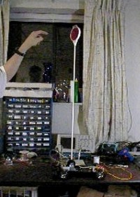
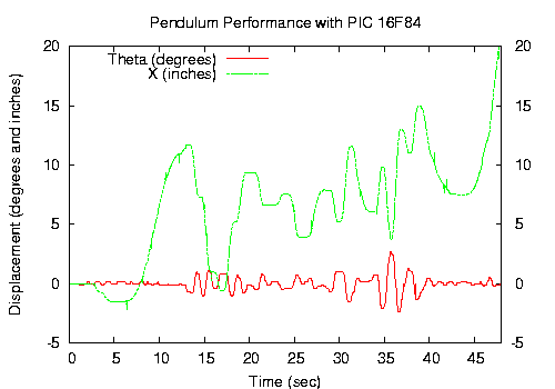
Stabilizing the inverted pendulum is *the* classic controls problem, introduced in the first week of each of the controls and dynamics classes I have taken (2.003, 2.004, 2.010 and 2.151). This page details my work wrestling with the inverted pendulum beyond theory and outside of the classroom. The Inverted Pendulum with a rotating baseMy first work on the inverted pendulum problem was for my undergraduate thesis: "Stabilizing an Inverted Pendulum with its base rotating around a horizontal axis." I extended the classic problem to handle a case where the pendulum base no longer moves in a line. The goal was to integrate this pendulum into an existing laboratory platform and enable undergraduate students to stabilize the inverted pendulum using simple components (op-amps and potentiometers). My thesis developed a model of the system, including a MATLAB simulation in simulink with a full state feedback controller. The integration of the actual pendulum with the 2.010 lab was unfortunately doomed to failure for many reasons, including a large dead-zone in the drive motor, noisy position and velocity measurements from the existing sensors and a noisy differentiation of the pendulum angle measurement. The theory developed and the circuits designed to compensate for these problems are detailed in my thesis. The Inverted Pendulum on a remote control car platformPhase two, after abandoning the pure analog control approach (but still resisting the thousand dollar gyroscope and DSpace board approach) was to tackle the problem using a remote control car platform and PIC 16F84 microcontroller. This project was in collaboration with Josh Pieper. The platform is a $15 Radio Shack remote control car. Optical encoders from 2 button mice were used as angle and position sensors. The resolution was good enough to stabilize the pendulum shown for as long as 5 minutes, with a characteristic slow oscillation. We were able to compensate for non-linearities, such as the drive motor dead zone with non-linear control code. Since the easiest way to model and understand the system is assuming force or acceleration inputs we designed first a velocity controller and then put another loop around that to approximate an acceleration control. We then used our digital position and angle measurements, and the derivative of these signals to implement approximate full state feedback. You can see the early performance in this preliminary video (with early code and still tethered to the power supply) with mpeg2 codec. The plot on the bottom shows the pendulum balancing for about a minute, until the x limit was reached. Data was aquired over the serial port, using an Atmel and an RS232 chip.
|
|
